


Fire tests
On 12 April 2019 in the Fire Testing Department of the Building Research Institute (ITB), the company AGS conducted comparative tests of ventilated facade fastening systems.
The tests were aimed at checking the behaviour of the respective solutions available in the market, in real conditions, in the aspect of the requirements specified in §225 of the Technical Conditions that should be met by buildings and their location, which has the following wording:
“Elements of facade claddings should be fastened to building structure in a way that prevents them from falling off during fire in the time shorter than resulting from the required fire resistance rating for the external wall, specified in §216, subparagraph 1, corresponding to the fire resistance class of the building in that they are fastened.”
The following sets of products were subjected to tests:
- passive brackets, from steel, in AGS system, in arrangement with a steel grid, with an innovative anti-corrosive coating,
- aluminium brackets without thermal insulation, with an aluminium grid,
- passive brackets from aluminium with aluminium grid (as thermal spacers of brackets the material was used with class of reaction to fire B-s3, d0; the material with class of reaction to fire C-s2, d0 was not used for comparative tests, because it is a weaker solution in terms of durability during fire).
In addition, the following rules were adopted in designing of the fragment of ventilated facade for testing:
- The sets of products in configurations listed above were installed directly above the test window (in its central part), so that on one half of the area exposed to fire they are placed in the layer of insulation from glass wool with density of ca. 20 kg/m3 and on the other half of thermal insulation in rock wool with density 48 kg/m3.
- A correct ventilation gap was assumed of at least 20 mm between the insulation and the claddings. Thus, both the part of the brackets, and the entire section of the grid protruded out of the insulation. It should be stressed that this aspect is frequently omitted in tests and test reports, and the brackets and grid systems are concealed in insulation, e.g. with high density. Such an arrangement does not conform to the facades actually constructed later on the building and it has a very serious impact on maintaining of durability of fastening in conditions of fire.
- The facade was not protected with additional fire boards from the bottom of operation of fire. During construction of facade in real conditions, in case of fastening of e.g. panels from sintered quartz or from fibre cement, the ventilation space of the facade opens very quickly and it is penetrated by fire, causing quick destruction of the supporting structure.
- As a cladding for a given set of products (1, 2, 3, 4, 5, 6 according to the drawing No. 1) one assumed the elements from GRC (glass fibre reinforced concrete) with a thickness of 20 mm, and each of them is fastened solely for a given solution of the supporting structure.
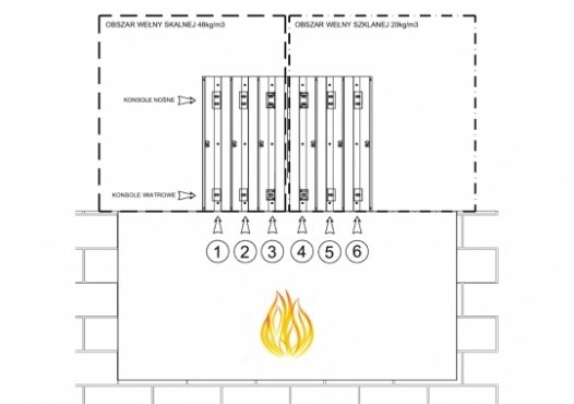
Drawing No. 1 Diagram of tested elements
Explanation:
- Aluminium brackets without thermal insulation, with an aluminium grid, in rock wool with density of 48 kg/m3.
- Passive brackets from aluminium, with an aluminium grid, in rock wool with density of 48 kg/m3.
- Passive brackets, from steel, in AGS system, in arrangement with a steel grid, with an innovative anti-corrosive coating, in rock wool with density of 48 kg/m3.
- Passive brackets, from steel, in AGS system, in arrangement with a steel grid, with an innovative anti-corrosive coating, in rock wool with density of 20 kg/m3.
- Passive brackets from aluminium, with an aluminium grid, in rock wool with density of 20 kg/m3.
- Aluminium brackets without thermal insulation, with an aluminium grid, in glass wool with density of 20 kg/m3.
THE TEST SIMULATED FIRE EXTENDING OUT OF THE WINDOW OF THE BUILDING INTO THE AREA OF HEADER AND UNDER THE WINDOW ZONE.
Course of testing:
- Already in the fifth minute in the set No. 5 the cladding chipped off and the aluminium grid melted.
- In the sixth minute fastenings in the set No. 2 and 5 were destroyed, supported on passive aluminium brackets in rock wool and glass wool.
- In the eleventh minute fastening was destroyed, supported on the set No. 6 – brackets and aluminium grid in glass wool.
- In the 25th minute the set No. 1 was destroyed – brackets and aluminium grid in rock wool.
Systems with aluminium brackets (passive and non-passive) and with an aluminium grid in rock wool were destroyed up to the top layer of thermal insulation.
Except for the elements described above, during the same test, the following solutions were examined, with the application of AGS fastenings:
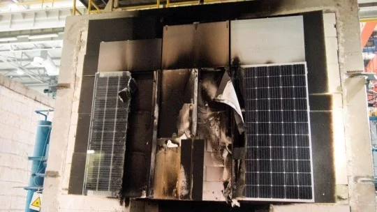
- frameless photovoltaic modules,
- framed photovoltaic modules,
- sintered quartz with a thickness of 3,5 and 5,5 mm,
- fibre cement board with a thickness of 10 mm,
- composite claddings.
All concrete claddings along with AGS fastenings kept their durability until the end of test.
CONDUCTED TESTS CONFIRMED DURABILITY IN CONDITIONS OF FIRE AND MEETING OF THE REQUIREMENTS OF §225 OF THE TECHNICAL CONDITIONS OF BUILDINGS WITH THE FOLLOWING WORDING:
“In the light of the requirements of §225 of the Regulation of the Minister of Infrastructure, for the solution connected with the application of an aluminium grid, according to the technical description, to be deemed safe, the possibility of burning of a fragment of a grid to the height of ca. 700 mm above the window opening / non-rated glazing in case of fire lasting for 60 minutes should be agreed with the Design Engineer.”
Photographs from the course of the research:
1
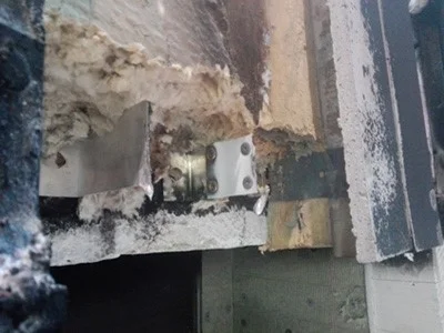
Photograph No. 1 Cross-section of the applied brackets directly above the opening simulating the header and under the window zone

2
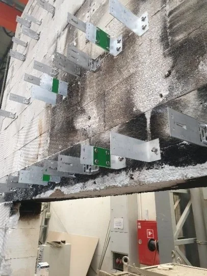
Photograph No. 2 View of the entire element for testing
3
Photograph No. 3 View of the aluminium brackets after testing
4
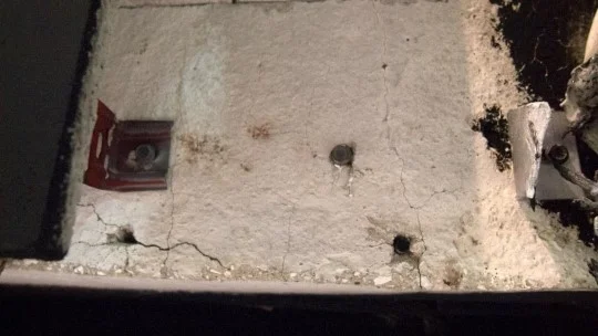
Photograph No. 4 View of the places where passive aluminium brackets were fastened in the glass wool. On the left side there is the undamaged AGS bracket
5
Photograph No. 5 View after examination of the test element, showing total destruction of aluminium elements of the supporting structure